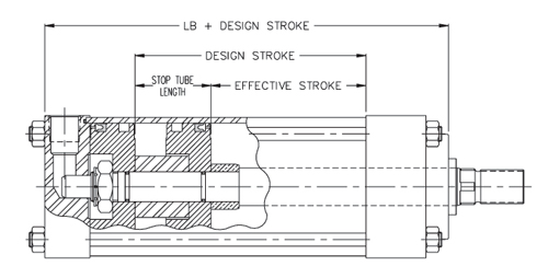
Two types of construction are used to satisfy Stop Tube requirements. The style suggested for use is dependent on certain cylinder specifications and the length of Stop Tube being considered.
The Spacer Style Stop Tube is recommended for use in all hydraulic cylinders when its length is under 6 inches, and with air operated models that do not include a rod end cush- ion.
Typical construction details which illustrate the rod mounted spacer located in front of a single piston are shown in the view below.
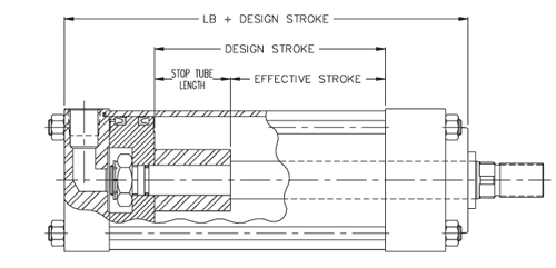
A Dual Piston Stop Tube consists of two pistons mounted on the rod separated by a confined spacer, with the overall length of the assembly made to suit order requirements.
While either style Stop Tube may be ordered, the Dual Piston type is recommended for use in all cylinders whenever the required length is 6 inches or more. It is mandatory, however, to use the Dual Piston style when a Stop Tube is required for an air operated cylinder having a cushion on the rod end.
Dual Piston construction is preferred for use because the wider piston assembly improves stability over the entire stroke length while the Spacer type is effective only when the cylinder stroke is fully extended.
Typical construction details are shown in the view below.
When ordering a cylinder equipped with a Stop Tube, it is necessary to provide clear information stating the desired requirements. A callout of the cylinder Design Stroke (effective stroke plus stop tube length), Stop Tube Length, and net Effective Stroke should be included to avoid possible misunderstanding of order specifications.
SELECTION OF OPTIONAL ROD BOOT:
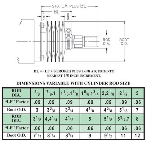
Rod Boots offer protection to the piston rod from harmful effects of severe operating environments and are available for all cylinders. When used, it is necessary to provide additional piston rod extension to allow space for the compressed boot length and end connections. The required extension varies with the rod diameter, stroke length, and boot cover material.
Cover materials suitable for a wide range of operating conditions are available. The standard boot material is a Neoprene coated nylon fabric of sewn construction suitable for use within a temperature range of -45o F to +220o F. Consult LYNAIR, INC. for information on available alternate materials.
The chart below provides data needed to determine boot envelope and rod extension dimensions. The given figures are related to the standard boot size used for each rod size. Other boot sizes with larger diameters having shorter closed length factors, or with smaller diameters having longer closed length factors are available for all rod sizes upon request. Consult LYNAIR, INC. for dimensional information pertaining to these alternate sizes if desired.
To determine the amount of additional Piston Rod Extension, multiply the charted “LF” Factor for the cylin- der rod size by the stroke length, add 11/ 8 inches for the end connections, and adjust answer to the nearest 1/ 8 inch incre- ment. The value produced is termed the “BL” dimension. This value must then be added to the standard “LA” dimension applicable to the given cylinder to determine the total piston rod projection. The adjusted value should then be designated as the required “LA” dimension for order information purposes.
The dimensional requirements described are illustrated in the view below.